Installation
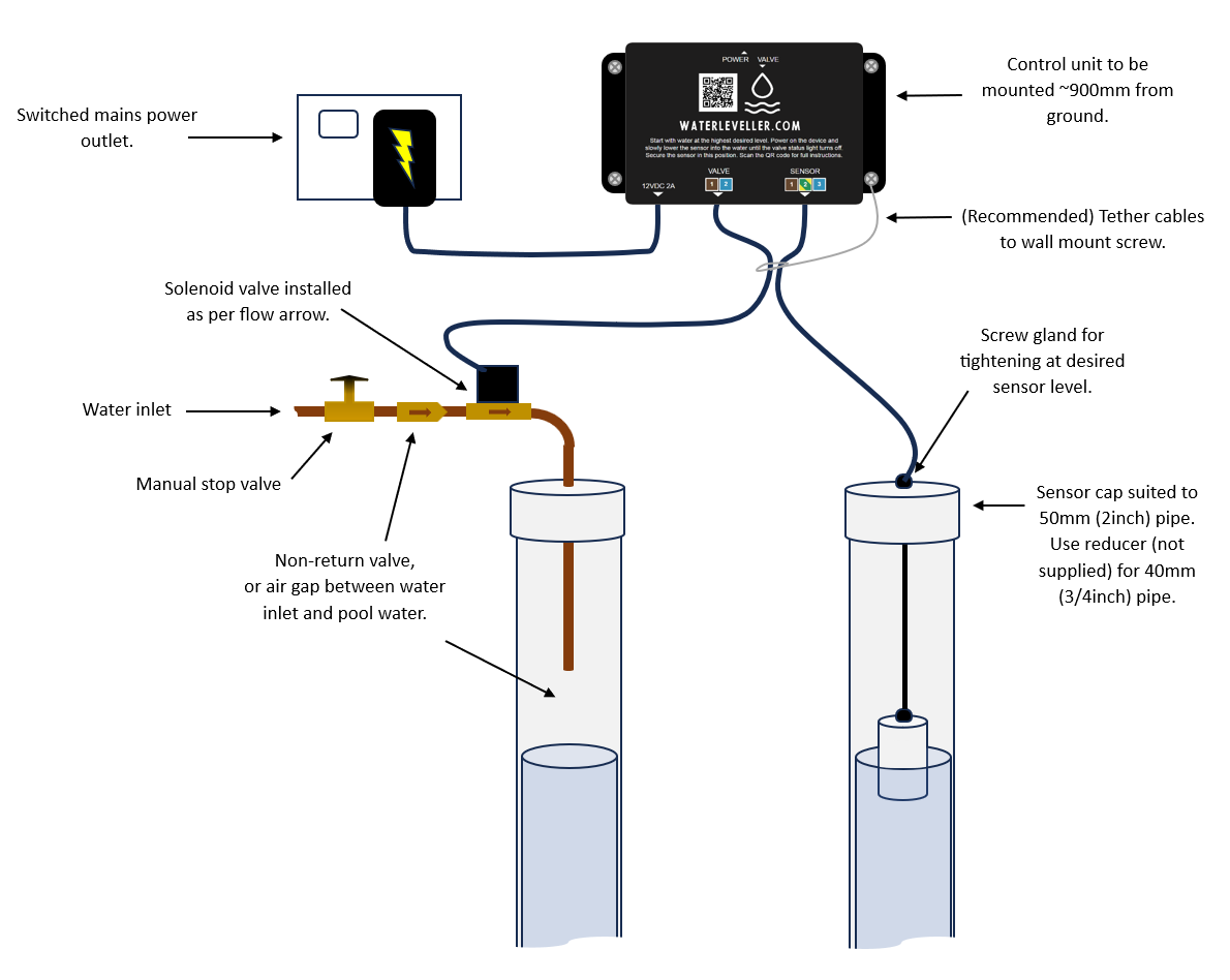
Reference diagram
General information
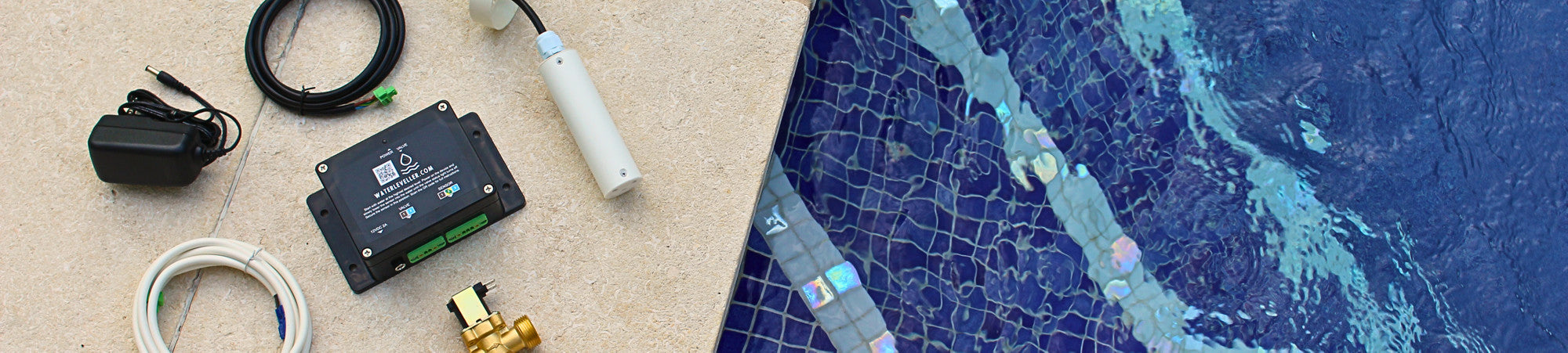
What's in the kit:
- Control unit
- Water level sensor and cable
- Solenoid valve and cable
- Power supply
Water Level Sensor Installation:
- Requires a vertical pipe, either 40mm or 50mm, running from the pool to the pool shed.
- The water level sensor has a cap suitable for a 50mm pipe. For a 40mm pipe, consider using a reducer (not provided) for an optimal fit.
Water Inlet:
- Requires a manual stop valve (not provided).
- If a dedicated water inlet pipe is used, ensure there's a sufficient air gap between the water inlet and pool water. This can replace the need for a non-return valve.
- Alternatively, if tapping into the filter return line, be sure to install a non-return valve (not provided) between the manual stop valve and the provided solenoid valve to prevent backflow.
Power Supply:
- A switched mains power outlet should be positioned at least 900mm above the ground, and in proximity to the control unit's intended location.
- The kit comes with a 1.8m power supply cable.
Control Unit Placement:
- Install near the pipes to be used and water inlet.
- Ensure the supplied solenoid and sensor cables (~2m in length) can reach their respective connections. These cables can be extended if needed.
Protective Installation:
- Ensure the kit is installed in a sheltered location, such as inside a pool shed.
- To avoid damage caused by accidental pulling of cables, it's advised to tether both sensor and solenoid valve cables to a wall mounting screw of the control unit.
Before Installation:
- Fill the pool to its highest intended water level.
Installation instructions
1. Setup the Control Unit:
- Mount the control unit approximately 900mm off the ground near the designated water inlet and pipes, following the diagram and recommendations.
- Ensure the mains power outlet is switched off, then connect the control unit to the supplied power supply.
2. Solenoid Valve Installation:
- Install the solenoid valve downstream of the stop and non-return valves (not included), as shown in the diagram.
- Connect the solenoid valve to the control unit using the provided blue-brown cable. Note: The solenoid valve's polarity is non-specific, so terminals can connect in any order.
- Attach the solenoid valve to the water inlet, ensuring the water flow aligns with the arrow on the solenoid valve. Connect it to the dedicated pipe leading to the pool (or filter return line). Open the stop valve. When the control unit is off, the solenoid valve should be closed, preventing water flow to the pool.
3. Water Level Sensor Installation:
- Before installation, ensure the pool is filled to the desired maximum water level.
- Connect the sensor to the control unit but avoid submerging it in the water level pipe.
- The provided sensor cap fits a 50mm pool pipe. For a 40mm pipe, consider using a reducer (not included). The sensor cable attaches to the cap using a screw gland. Loosen this enough to move the sensor cable through easily.
- Mount the sensor to the water level pipe using the provided cap. The sensor should sit above the water level for now.
4. Calibrating the Sensor:
- Power on the control unit at the mains switch. The power and valve status lights should illuminate, initiating water flow through the solenoid valve into the pool.
- Gradually lower the sensor into the water level pipe. Once the valve status light turns off, signalling the upper water level has been achieved, secure the sensor at this depth by tightening the screw gland on the cap.
Note: The water must drop about 20mm below the preset upper level before the valve status light activates and the solenoid valve opens. The valve will close and the light will turn off once the water returns to this upper level.